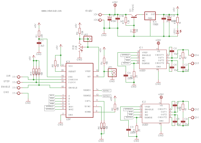

The definitions of high/low are determined by your opto endstop. This is the signal from the 'max' sensor. This is the signal from the 'min' sensor. A high signal means on, low signal means off This pin allows you to turn the motor on and off. If this pin is high, the motor will rotate forward, low it will rotate backwards. That will reduce power usage, and will prevent your motor from overheating.Ĭonnect this to Arduino to share a common ground.Ī pulse on this line will make the stepper motor advance one step in the desired direction. Generally, you will want to adjust this to the lowest setting you need that will still turn the motor. Adjusting it to the lowest setting will cause the motor to stop turning. Generally this will be clockwise/counter clockwise, but it will be obvious which is which as you adjust the current with the motor running. Simply turn the trimpot one direction to get the minimum current, and the other direction to get maximum current. The board allows you to control the amount of current flowing through the coils by adjusting a trimpot located on the board below the 'Max' header.
#Stepper motor driver ic l297 schematic full#
Half stepping means the stepper takes twice as many steps, whereas full stepping means the stepper takes its normal number of steps. Generally you will only want to select the stepping mode once, at the very beginning of board construction. Use enough solder to bridge the two pads. You connect the center pad to either the left or the right pad to select the state of the jumper. You need to select a stepping mode for your board to run!
#Stepper motor driver ic l297 schematic how to#
You can configure this current by setting the trimpot on the board and measuring the voltage on the test point.Īt the bottom of the page is a section showing how to run this board off a single 12v supply. The L297 will sense the amount of current flowing through the coils, and will 'chop' the signal to the L298 so that the average current flowing is the desired amount. One interesting feature of the L297 is its current sensing and 'chopping' abilities. The L298 is capable of driving up to 2A per coil. The L297 takes the signals from your microprocessor and translates them into stepping signals to send to the L298 which actually drives your stepper motor. It is based around the L297/L298 stepper driver combo. This board allows you to control one stepper motor, as well as receive input from two limit switches.


 0 kommentar(er)
